


O-ring
Key Word:
Category:
Details
Product Introduction
O-rings refer to rubber rings with an "O"-shaped cross-section. It is one of the more widely used hydraulic and pneumatic transmission systems. Mainly used for mechanical parts to prevent leakage of liquid and gaseous media under static conditions. In some cases, O-rings can also be used as dynamic sealing elements for axial reciprocating motion and low-speed rotational motion. It has simple structure, convenient installation, low cost, easy maintenance, and various materials. It can be used as a seal for various fluids such as oil, water, and gas. According to different conditions, different materials can be selected to suit it.
From the perspective of the sealing principle, the O-ring seal is a kind of squeeze type seal. The basic working principle of the squeeze type seal is to rely on the elastic deformation of the seal to cause contact pressure on the sealing contact surface. The contact pressure is greater than that of the sealed medium. If the internal pressure is used, no leakage occurs, and vice versa.
|
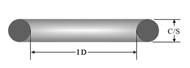
Marking method O-ring specification representation method: inner diameter * wire diameter (ID*C/S) |
 |
|
Skills requirement
Working conditions
Working pressure: 0~70Mpa (retaining ring is required for high pressure)
Speed: the maximum reciprocating speed can reach 0.5m/s, the maximum rotation speed can reach 2.0m/s
Operating temperature: -60℃~320℃
Working medium: all kinds of lubricating oil, liquid and gas
The relationship between material hardness and working pressure
The hardness of the O-ring is directly related to whether it can withstand pressure. Under normal circumstances, the higher the hardness of the O-ring, the stronger its ability to withstand high pressure.
| Hardness (Shore A)/degree | 50±5 | 60±5 | 70±5 | 80±5 | 90±5 |
| Working pressure static seal/Mpa ≤ | 0.5 | 1 | 10 | 20 | 50 |
Speed ≤0.2m/s)/Mpa ≤ |
0.5 | 1 | 8 | 16 | 24 |
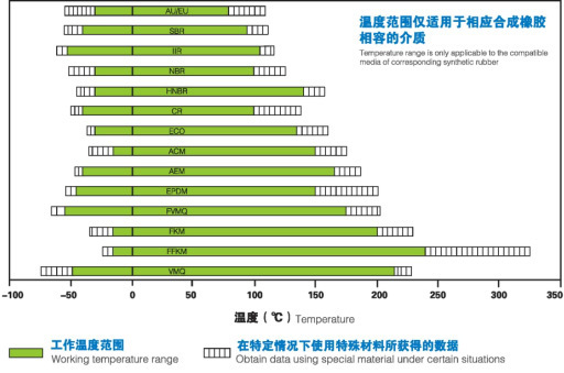
Operating temperature range of different synthetic rubbers
The existing various synthetic rubber materials can meet the operating temperature of O-rings under different conditions. According to the working conditions of the product, the O-ring rubber material suitable for its temperature can be selected.
Structural design
Dimension tolerance standard table: unit (mm)
|
|
|
||||||||||||||||||||||||||||||||||||||||||||||||||||||||||||||||||||||||||||||||||||
| Inner diameter tolerance standard table 1 | Inner diameter tolerance standard table 2 | Wire diameter tolerance standard table |
Groove design
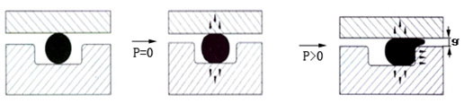 The O-ring in the groove will deform under the pressure of the medium, and the edge of the O-ring will flow into the gap to achieve the O-ring sealing function. The greater the pressure on the O-ring, the greater the deformation of the O-ring, the better the sealing effect of the O-ring will be obtained. When the pressure of the O-ring exceeds its bearing limit, the O-ring will be squeezed into the gap, causing the O-ring seal to fail. Therefore, the O-ring groove design must be reasonable.
Extrusion gap
The maximum allowable extrusion gap gmax is related to the system pressure, the cross-sectional diameter of the O-ring and the hardness of the material. Generally, the higher the working pressure, the smaller the maximum allowable extrusion gap gmax. If the gap g exceeds the allowable range, it will cause the O-ring to squeeze out or even be damaged.
Compression set
Another indicator for evaluating the sealing performance of O-rings is the compression set of the selected material. Under pressure, the O-ring, which is an elastic element, produces elastic deformation, and as the pressure increases, permanent plastic deformation will also occur. The compression set d can be determined by the following formula:

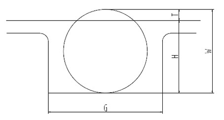
In the formula: b1-original thickness (ie cross-section diameter W) b1-thickness under compression b2-thickness after release
Generally, in order to prevent permanent plastic deformation, the maximum allowable compression of O-rings is about 30% in static seals and about 20% in dynamic seals.
|
Compression rate and fill rate setting E (%): compression ratio |
 |
|
Compression ratio setting--------------------------------------------- -------------------------------------------------- --------------
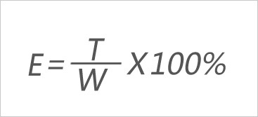 Use range:
8%-30% (dynamic seal: 8%-20%; static seal: 15%-30%)
Fill rate setting--------------------------------------------- -------------------------------------------------- --------------
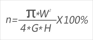 Use range:
max90%, design target value 75%
Recommended O-ring groove size
Unit (mm)
| Section diameter | Radial dynamic and static | Limited to shaft seal | radius | |||||
| Groove depth e1+0.06 |
Groove width | |||||||
| g0+0.2 | Retaining ring g1+0.2 |
Retaining ring g2+0.2 |
Groove depth e2+0.2 |
Groove width g+0.2 |
Unblocked Circle r | With retaining ring r | ||
| 1.20 | 0.80 | 1.40 | - | - | 0.65 | 1.40 | 0.20 | - |
| 1.25 | 1.00 | 1.80 | - | - | 0.85 | 1.80 | 0.20 | - |
| 1.52 | 1.20 | 1.90 | 2.90 | 3.90 | 1.00 | 2.10 | 0.20 | 0.20 |
| 1.78 | 1.45 | 2.20 | 3.60 | 5.00 | 1.20 | 2.40 | 0.40 | 0.20 |
| 1.80 | 1.45 | 2.20 | 2.60 | 5.00 | 1.20 | 2.40 | 0.40 | 0.20 |
| 1.90 | 1.65 | 2.50 | 3.90 | 5.30 | 1.40 | 2.50 | 0.50 | 0.30 |
| 2.40 | 2.00 | 2.90 | 4.30 | 5.70 | 1.70 | 3.20 | 0.50 | 0.30 |
| 2.62 | 2.25 | 3.10 | 4.50 | 5.90 | 1.90 | 3.60 | 0.60 | 0.30 |
| 3.50 | 3.10 | 4.20 | 5.60 | 7.00 | 2.70 | 4.80 | 1.00 | 0.40 |
| 3.53 | 3.10 | 4.20 | 5.60 | 7.00 | 2.70 | 4.80 | 1.00 | 0.40 |
| 5.33 | 4.70 | 6.20 | 7.90 | 9.60 | 4.30 | 7.10 | 1.20 | 0.40 |
| 5.70 | 5.00 | 6.70 | 8.40 | 10.10 | 4.60 | 7.70 | 1.20 | 0.60 |
| 7.00 | 6.10 | 8.20 | 10.70 | 13.20 | 5.80 | 9.50 | 1.50 | 0.60 |
| 8.40 | 7.50 | 9.70 | 12.20 | 14.70 | 6.90 | 11.70 | 2.00 | 0.60 |
| If larger expansion is required, the groove width can be increased by 20% | ||||||||
MESSAGE
Address
Room 2211, Building A, Fenglin International, Central City, Longgang District, Shenzhen
©2024 Shenzhen Oxk Rubber Technology Co., Ltd. Powered by www.300.cn Official Website Supports Ipv6